Plastic injection molding is a nuanced process. It demands precisely tooled components and tightly controlled variables to produce high and consistent quality parts.
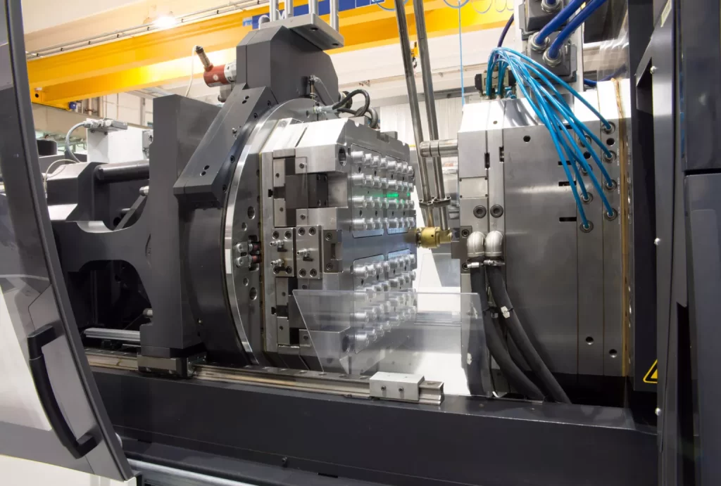
There are many components of the injection molding machine that operate in sync to perform the same melt, inject, and mold action on repeat and product plastic parts.
Each of these components must be designed to perfection to ensure the plastic part comes out just as needed. One of these vital parts lies at the very edge of the mold cavity. This is the gate.
Seemingly small and insignificant, the gate plays a vital role in how the plastic injection molding process goes. Incorrect gate design can introduce delays in the process and lead to inefficient results.
This is why, understanding gate design guidelines and taking them into account is critical before you proceed with your mold tooling and production.
What is the Gate in Injection Molding?
The gate is a part of the runner system and serves as an entryway for the molten plastic into the mold cavity. It controls the flow and volume of molten plastic and is responsible for ensuring proper filling and formation of the part.
Gates are strategically designed and placed within the system according to the part requirements, finish, and design to optimize the molding process and ensure part quality.
Since gates channel molten plastic into the cavity, the molten plastic solidifies within the gates as well during the cooling stage. The part then cools with the gate still attached to it. And another step is needed to remove the gate from the part. This step is called degating or trimming.
Gates can be trimmed manually after the part has been removed from the machine or automatically during ejection.
Whether the trimming will be manual or automatic depends on the type of gate used in the process, as we will discuss in the next section.
Types of Gates Used in Injection Molding
Besides impacting part form and finish, gates also influence the process variables. Therefore, choosing the right gate is an important design consideration when tooling the mold.
Before you can choose the right gate for your mold, you must understand some of the most common types of gates that are available out there.
Below is a quick overview of some of these gates that are often used in injection molding:
Sprue Gate
Sprue is the channel that feeds the molten plastic into the runner system. The Sprue Gate sits at the end of the Sprue and allows the molten plastic to come directly from the Sprue and go into the mold cavity.
Sprue Gate is essentially the absence of a gate. This type of gate, though easy to implement, eliminates the need for a runner system. It can also produce high tensile stress around the gate.
A Sprue Gate is mostly used for single cavity molds and parts that do not have aesthetic requirements. It is manually trimmed from the part once the part is cooled, solidified, and removed from the mold.
Edge Gate
As the name suggests, an edge gate appears at the edge of the part. Also known as a Tab Gate or side gate, it can only be used for flat parts and parts that demand easy trimming since the gate itself is thin and can be easily trimmed.
Degating in this type of gate is manual, which can add to the process turnaround time.
Pin Gate
The Pin Gate is placed on the B-side of the mold. The gate itself is very thin but has a high scrap rate because the runner is so large compared to the gate.
Since the gate point is thin, Pin Gate is ideal for intricate parts where minimizing gate vestige and marks is crucial.
The gate is auto-trimmed and removed automatically as the part ejects the mold.
Hot Runner Gates
A hot runner system maintains the state and temperature of the molten plastic as it goes from the barrel and into the mold cavity. Two types of gates are commonly used with hot runner systems:
- Thermal Gates
- Valve Gates
Thermal Gates act like your regular gates and direct the flow of molten plastic from the runner to the mold cavity. This type of gate is susceptible to gate vestige and the part may require post-process finishing.
Valve Gates have pins placed within to offer an additional level of control to the flow of the molten plastic. The pins are pulled back to allow for the material to flow and pushed forward to cut the flow off.
Valve Gates promise low gate vestige and increased process efficiency.
Diaphragm Gate
A diaphragm gate is used when concentricity is an important part requirement and usually appears during the production of cylindrical parts that are open at both ends.
Diaphragm Gates, when used in the right cases, prevent the formation of defects like weld lines and help improve end part quality.
Fan Gate
Fan Gate, just as the name suggests, looks like a fan. It is narrow on the runner end and widens towards the part end. These gates are attached to the part at the parting line and require minimal trimming.
Fan Gates may be used to establish a stable flow of molten plastic into large parts.
Tunnel Gate
A tunnel or submarine gate is placed below the parting line and allows for automatic trimming during ejection. It tapers off close to the part region of the gate and breaks away from the part without excessive vestige.
Cashew Gate
Cashew Gate is similar to a tunnel gate in that it is machined below the parting line and is trimmed automatically. The difference lies in the structure as the Cashew Gate is curved, which makes ejection more difficult. However, it allows gating in areas that may be impossible to reach with a tunnel gate.
Important Design Guidelines for Injection Molding Gates
A gate may be small, but the role it plays in the plastic molding process is huge. Right gate design minimizes post-processing and allows even distribution of the molten plastic within the mold cavity. This makes the gate a key player in preventing or facilitating part defects.
Here are three important design guidelines for you to consider and ensure your gate helps increase the efficiency of the molding process rather than taking away from it:
Gate Size
Incorrect Gate Size can lead to part defects such as jetting. Jetting is when the molten plastic sprays into the mold cavity instead of flowing smoothly into it.
Gate size also influences the surface finish of the end part. A smaller gate may be easier to remove from the part and leave minimal vestige. However, pressure may increase at the edge of a smaller gate as molten plastic goes through it, resulting in increased stress.
Ideally, you should select your gate dimensions to make sure the gate facilitates complete packing within the part, allows molten plastic to flow into the cavity easily, and does not increase plastic pressure too much at the entry point.
If the design demands smaller gate dimensions, you can choose a gate type that is inherently small like the Pin Gate.
Gate Location
The point where the molten plastic goes through the gate and enters the cavity is called the gate location. This is another vital design consideration when choosing the right plastic injection molding gate.
Certain gates are difficult to trim and prone to leaving vestiges like the Thermal Gates. And some gates offer low-level cosmetic finish. This is why, deciding the gate location as per the part requirements is vital before you move forward with tooling and production.
Improper gate location can also lead to mold defects like fractures, uneven thickness, flashing, etc. Since gates are high-stress areas, they can also lead to stress marks on the finished parts.
You must take all of these considerations into account before deciding on a gate location.
Generally, the gate should be placed in the deepest cross-section of the cavity, closed to thick-walled areas, and away from any pins or obstructive objects.
You should also ensure that the gate location does not affect part aesthetics or make degating a trouble.
Form and Surface Finish of the Part
We now know how gate placement and size as well as the type of the gate greatly influence the form and finish of the part. Therefore, before you get going with gate design, study the part design closely and understand its requirements.
If the part requires a clean, aesthetic finish, you may want to keep the gate small and away from any visible part regions.
Besides that, the shape of the finished part may also have unique gating requirements. For example, you may want to use a Diaphragm Gate when producing cylindrical parts and a pin or cashew gate when working with smaller, more intricate part designs.
Conclusion
Your injection molding gate design can make or break the efficiency of the entire process. Improper gate selection and design can lead to part defects, vestige, flow back of molten plastic into the runner, and many other complications that may reduce the part quality and increase the production cost.
Therefore, considering design guidelines before you go ahead and tool the gate is critical.
There are three important design guidelines that you must take into account. These include gate size, location, and finish of the part. Each of these factors influences the gate design and when done incorrectly can lead to part defects and processing delays.
